2D Frame Analysis Dynamic Edition 7.2.8 Crack + License Key Download
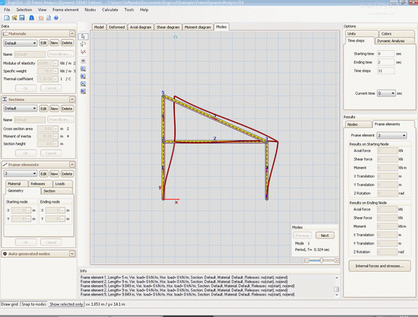
Frame Analysis Dynamic Edition is a useful civil engineering application which performs static and dynamic analysis of frames and trusses using the finite element method. The interactive, easy and versatile UI allows quick drawing of the model.
Here are some key features of "2D Frame Analysis Dynamic Edition":

Download 2D Frame Analysis Dynamic Edition Crack
| Software developer |
EngiSSol
|
| Grade |
4.1
1015
4.1
|
| Downloads count | 8487 |
| File size | < 1 MB |
| Systems | Windows All |
· Option to perform static or dynamic analysis
· Dynamic Preferences, such as ending time of loading, integration step, damping coefficient and initial speeds - displacements
· Ability to insert a math function of variable t (time) as the dynamic load of each node, for example node 34: p(t) = 300*Sin(15*t), node 5: p(t) = 5*x^3 + 2*x^2
· Ability to modify the loading table manually (columns - degree of freedom, rows- time) in order to insert custom loadings p(t)
· Creation of non diagonal mass matrix
· Arithmetic calculation of all eigenvalues and eigenvectors
· Computation of the dynamic displacements and creation of graphs of each node's displacements in the selected time span
· Drawing diagrams of Axial and Shear Force and Bending Moment and deformed shape because of the dynamic loads at a specified time
· Use of highly flexible, general, finite element method
· Static Analysis of Multi span beams, 2D Trusses and 2D Frames
· Unlimited number of Nodes and Beams
· 3 Degrees of freedom per Node, 6 per Beam
· Compatibility with any consistent system of units
· All type of boundary conditions (fixed, rollers, etc.)
· Bent support conditions with respect to the global coordinate system, e.g. roller at 30 degrees in Node #4.(Nodal constraints in all directions)
· Separate Coordinate System for each node
· Rotational Springs
· Unlimited number of translational around a node (direction and stiffness for each one)
· Consideration of any translational and rotational displacements of the support conditions
· No need to define first Nodes and then Beams, Nodes are produced automatically
· Consideration of thermal loads
· Ability to modify the beam material properties easily and fast
· Static Load is given with respect to the global or local system of each beam or Node
· Quick release 1 to 3 degrees of freedom at the starting or ending node of each beam in a user defined local coordinate system
· Vertical and Horizontal Distribution Load on beams
· Easy and interactive insertion of Arcs
· Quick drawing of the model in a user friendly environment
· Full GUI including zoom, pan, grid, snap options
· Calculation and Drawing of the deformed shape of the given model
· Analytical view of the results of analysis, the geometry, the static model, the loads etc.
· Drawing of Diagrams of Axial and Shear Force and Bending Moment
· Scaling to above diagrams and the deformed model interactively
· Printings of analytical results, stress and displacements diagrams
· Library with the major steel section shapes as well as typical concrete grades
Requirements:
· Microsoft .NET Framework 1.1
Limitations:
· 5-node trial
